TM 3-4240-241-12
e. After the shelter and the filter unit have been
inspected, report the deficiencies to direct support
70. Inlet Damper Adjustment
maintenance personnel.
Adjust the inlet damper when there is a need to
f. To test the canister, start the filter unit motor or
increase or decrease the airflow in the improvised CBR
engine and after a warmup period, check the air
protective shelter (TM 3-350). To increase the airflow,
pressure in the shelter (TM 3-350).
open the inlet damper (1, fig. 13) by moving the damper
g. Adjust the speed of the gasoline engine as
control handle (2) counterclockwise. To decrease the
necessary (TM 5-2805-206-14) to maintain the positive
airflow, close the inlet damper by moving the damper
pressure of filtered air within the shelter.
control handle clockwise.
h. Adjust the inlet damper as necessary.
Section VII. BLOWER GASKET
adhesive.
71. Description and Function
(2) Connect the elbow connector assembly or
The blower gasket is cemented in the recess of the
the air inlet hose assembly and check for
locking coupling adapter. It provides the necessary seal
proper fit and installation of the gasket.
against air leaks when the locking coupling adapter is
connected to either the elbow connector assembly or the
air inlet hose assembly.
72. Maintenance
Organizational
maintenance
personnel
are
authorized to replace the blower gasket.
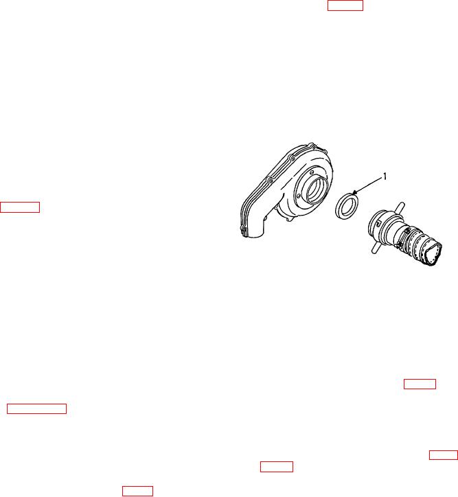
a. Removal. (Fig. 21)
(1) Disconnect the locking coupling (4) from
the locking coupling adapter (2).
(2) Pry the gasket (3) out of the recess of the
adapter.
b. Inspection and Maintenance.
1
Blower
3 Blower gasker
(1) Clean the surfaces of the adapter and
2
Locking coupling
4 Locking coupling
remove all particles of remaining cement.
adapter
5 Locking coupling tube
(2) Wipe the inner ring with drycleaning
solvent. Inspect inner surface for damage.
Figure 21. Blower inlet and blower gasket.
c. Installation.
(1) Cement (MIL-A-3562) the gasket (3) in the
recess of the adapter with liquid rubber
Section VIII. CANISTER ASSEMBLY
b. Remove eight turnbuckles (10, fig. 4), which
73. Description and Function
fasten manifolds and filters together, by loosening
The description and function of the canister
turnbuckle screws.
assembly is given in paragraph 5.
c. Loosen four hose clamps (5, 7, 13 and 16) which
74. Maintenance
fasten two air duct hose (6 and 15).
Organizational
maintenance
personnel
are
d. Extend the four retractable carrying handles (14)
authorized to replace the gas filter, particulate filters,
and carefully lift top manifold (4) with engine (2, fig. 1) or
hose assemblies, and the associated hardware.
motor (2, fig. 2) and blower (3) attached. Place on
75. Disassembly
wooden blocks, being careful not to dent or scratch
Stop engine or motor and perform the following steps:
manifold surfaces.
a. Remove air inlet hose assembly (1, fig. 1) and
air outlet hose assembly (4).
33

