
d. Idle Adjustment Needle.
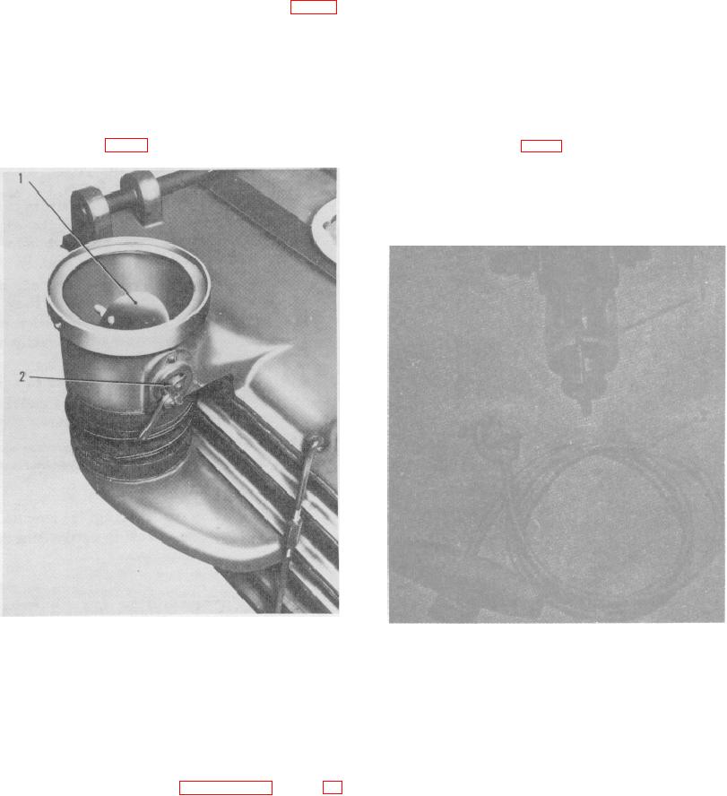
let and is controlled by the damper
control handle (2).
Purpose. The canister inlet damper
(1) Location. The idle adjustment needle (1, fig. 12)
(2)
regulates the flow of air into the
is located on the upper carburetor body.
canister. It is set at the factory to
deliver 800 cubic feet of air per
(2) Purpose. The idle adjustment needle is used to
minute.
adjust the fuel-air mixture at idling speed.
e. Canister Inlet Damper.
11.
Engine Ancillary Assemblies
a. Starting Rope Assembly.
Location The canister inlet damper (1,
(1)
(1) Location. The starting rope assembly
fig. 13) is located in the canister air in-
(2, fig. 14) is packed separately and
crated with the filter unit.
(2) Purpose. The starting rope assembly
is furnished for manually cranking the
engine and must be kept with the
engine at all times.
1
Inlet damper
2
Damper control handle
1. Fuel filter
2
Starting rope
Figure 13. Canister inlet damper.
Figure 14. Gasoline engine ancillary assemblies
Section II. OPERATION UNDER USUAL CONDITIONS
for additional instructions covering operation of the
12.
General
apparatus in extremes of climate and adverse
This section contains instructions for operating the
environmental conditions.
ABC-MI6A1 filter unit under normal conditions of climate
(50F. and above). Refer to paragraphs 17 through 21
13