with hose clamps (3).
(2) Air outlet hose assembly. The air outlet
hose assembly consists of an intake
manifold (8), gasket (7), air duct hose (4)
and air outlet screen assembly (1)
consisting of an adapter and screen
attached by rivets and washers. The intake
manifold and the air outlet screen assembly
are fastened to the air duct hose with hose
clamps (3).
(3) Elbow connector assembly. The elbow
connector assembly (6), is connected
between the blower air inlet and the
canister air outlet when the filter unit is
operated inside the CBR protective shelter.
For outside installation, the elbow is
connected to the canister air outlet and the
air outlet hose assembly.
6. Identification
a. The ABC-M6A1 gasoline engine driven filter unit
has two identification plates. The engine identification
plate (A, fig. 9) furnishes information as to make, model,
serial number, Federal Stock Number, and other
pertinent maintenance data for the Military Standard
gasoline engine. This identification plate is mounted on
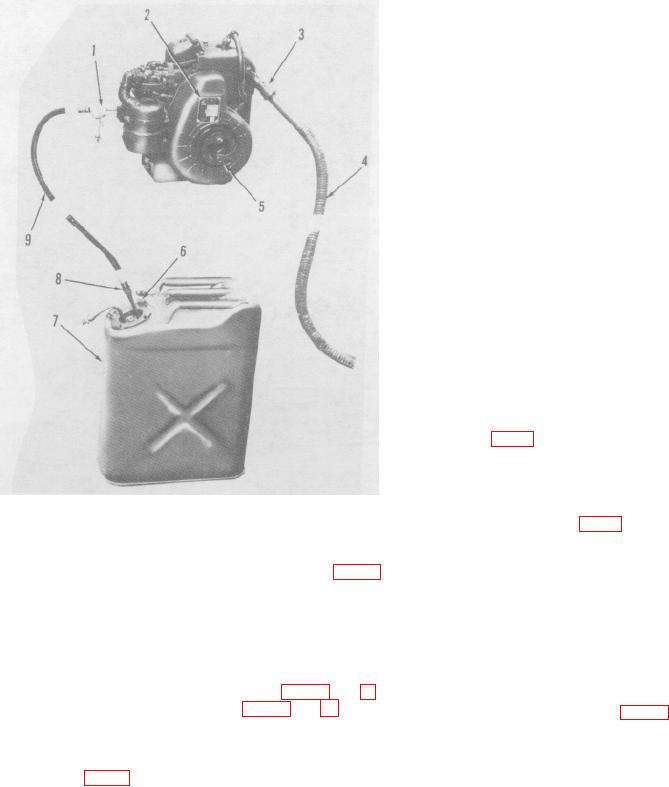
Figure 7. Gasoline engine and component parts.
the flywheel cover of each engine. The filter unit
identification plate (B, fig. 9) furnishes information as to
e. Electric Motor Installation. The electric motor
make, part number, Federal Stock Number, serial
driven ABC-M6A1 filter unit is powered by a 1
number, manufacturer, and other pertinent information
horsepower general-purpose electric motor (2, fig. 2)
for the filter unit.
mounted on a motor stand assembly. The motor
operates on 115- or 230-volt, 60cycle, single-phase
b. The ABC-M6A1 electric motor driven filter unit
alternating current.
has two identification plates. The motor identification
plate furnishes information as to make, model, serial
f. Hose assemblies and Elbow Connector
number, Federal Stock Number, and other pertinent
Assembly. The hose assemblies used with the filter unit
maintenance data for the electric motor.
This
identification plate is mounted on the electric motor. The
filter unit identification plate (fig. 10) furnishes information
as to make, part number, Federal Stock , Number, serial
(1) Air inlet hose assembly. The air inlet hose
number, manufacturer, and other pertinent information
assembly consists of a cover assembly (2,
for the filter unit.
fig. 8), locking coupling assembly (5) and
an air duct assembly (4).
The cover
assembly and the locking coupling
assembly are fastened to the air duct hose
9

