
TM 3-4240-284-208P
2-12. PROTECTIVE ENTRANCE CONTROL MODULE - MAINTENANCE INSTRUCTIONS (CONT).
LOCATION
ITEM
ACTION
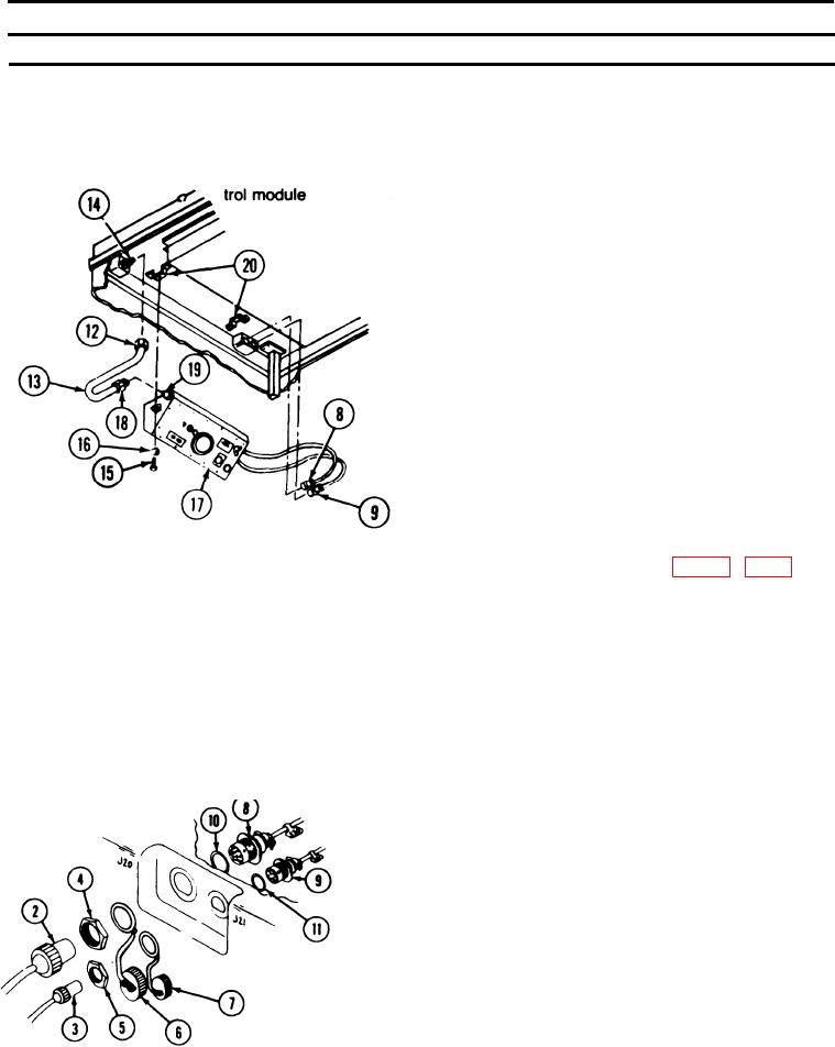
REMOVAL (CONT)
Disconnect adapter (12) on hose (13) from coupling
(14).
M10 Protective Entrance
Protective entrance con-
Remove screws (15) and washers (16).
Remove protective entrance control module (17) from
inside the protective entrance.
CAUTION
Pressure circuit may be damaged. Hold
coupling on protective entrance control
module with a wrench to prevent it from
turning.
Disconnect adapter (18) on hose (13) from adapter(19)
on protective entrance control module.
REPAIR
Fabricate replacement hose (13) (fig E-4A, app E). Cut
Hose
adapters (12 and 18) from hose and insert adapters in
new hose.
INSTALLATION
Install hose on protective entrance control module. Hold
Protective entrance con-
M10 Protective
trol module
adapter (19) with a wrench and tighten adapter (18).
Entrance
Position protective entrance control module (17) against
brackets (20) in protective entrance.
Install screws (15) through washers (16) and into brac-
kets (20). Tighten securely.
Install adapter (12) on coupling (14) and tighten.
Install electrical cable connectors J21 (9) and J20 (8)
with prefortned packings (10 and 11) in protective
entrance from the inside.
2-64