
TM 3-4240-284-20&P
ACTION
ITEM
LOCATION
From the outside, install loop of connector cover (7) and
nut (5) on cable connector J21 (9). Tighten nuts
securely. From the outside, install loop of connector
cover (6) and nut (4) on cable connector J20 (8). lighten
nut securely.
Reconnect electrical cable plugs P20 (2) and P21 (3).
REMOVAL
INSTALLATION
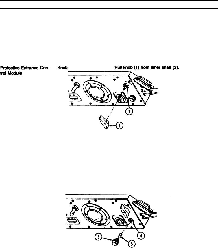
Aline knob pointer with 0 on panel. Push knob (1) on
timer shaft (2).
REMOVAL
PURGE indicator lamp
Protective Entrance Con-
Unscrew indicator light (3) from indicator Iight base (4).
trol Module
Pull out lamp (5) from indicator light (3).
INSTALLATION
Insert indicator lamp (5) in indicator light (3).
Install indicator Iight (3) in Iight base (4).
2-65