
Probable cause
Possible remedy
35.
Electric Motor Fails to Start
Incorrect line voltage ---- Check line voltage
Probable cause
Possible remedy
Blown fuse ----------------- Replace fuse.
Open connection in con- ---- Check plug connection
Motor jammed ------------ Report to general support
nector plug.
maintenance personnel.
Open wiring in cord----------- Replace cord.
Section V. BLOWER ASSEMBLY
36.
General
37.
Description and Function
This section and the following sections contain
The description and function of the blower assembly
information useful to the operator in performance of
is given in paragraph 5.
operator's level maintenance on the ABCM6AI filter unit.
Instructions for each unit or part that the operator is
38.
Maintenance
authorized to remove, disassemble, clean, inspect,
The operator is authorized to rotate the blower
assemble, adjust and install are found in these sections,
assembly for either inside or outside operation. It is also
with the exception of those instructions found elsewhere
his responsibility to see that the proper hookup of the
in this manual.
blower assembly with the attaching assemblies is made
before operating the filter unit.
Section VI. CANISTER ASSEMBLY
39.
General
The canister- assembly consists of the filter and
manifold components through which the air passes for
40.
Description
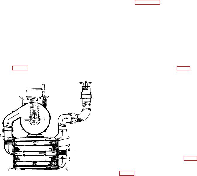
purification (fig. 15). Four filters, three manifolds, and
These intake manifold (12, fig. 4) is located in the
two air duct hoses are the principal parts of the canister.
center of the canister. The four filters, consisting of two
gas filters (11) and two particulate filters (8), are
arranged so that one gas filter and one particulate filter
are stacked on either side of the intake manifold. The
particulate filters (8) are adjacent to the intake manifold,
and the two gas filters (11) are next in order. ']The top
and bottom of the canister consists of tile top manifold
(4) and bottom manifold (9), respectively. The manifolds
and filters are held together by eight turnbuckles (10).
The air inlet (1) is connected to the air inlet manifold by a
fabric air duct hose (15) which is attached by two hose
clamps (13 and 16). The top and bottom manifolds are
connected by a fabric air duct hose assembly (6) which is
attached by hose clamps (5 and 7). The top manifold
contains a swivel base (2) to which the gasoline engine
or electric motor is mounted. Four retractable carrying
handles (14) are mounted in fittings on the top manifold.
The elbow connector assembly (6, fig. 8) connects the
canister air outlet to the blower air inlet when the filter
unit is connected for inside operation. An inlet damper
(1, fig. 13) is mounted in the air inlet and is adjusted for
1 Top manifold
5 Particulate filter
proper opening by the damper control handle (2).
2 Gas filter
6 Gas filter
3 Particulate filter
7 Bottom manifold
4 Intake manifold
Figure 15. Filter arrangement and air flow in canister.
20