
Check tapped holes for stripping or cross-
(2) Position two spacer blocks (2) between
threading.
gasoline engine and engine stand
assembly with chamfered edges toward
engine.
c. Repair.
(3) Install six 1 3/8-inch long capscrews (5)
and lockwashers (4) through engine stand
(1) Repair cracks in engine stand assembly
assembly and spacer blocks and screw
by inert gas welding. Dress all welds if
into engine.
required to prevent interference. Chase
(4) Install six 3/4-inch long capscrews (6) and
cross-threaded holes with a 3/8-16 UNC-
lockwashers (4) in opposite side.
2B tap.
Assemble and install blower assembly as
(2) Repair for the gasoline engine is
described in paragraph 14d.
contained in TM 5-2805-206-14.
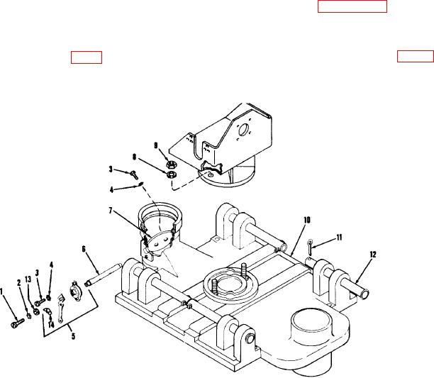
(5) Place engine, stand assembly, and blower
d. Assembly and Installation.
assembly as one unit on swivel base of
top manifold assembly and secure with
two self-locking nuts (9, fig. 4) and
(1) Place gasoline engine (1, fig. 3) on engine
washers (8).
stand assembly.
8. Washer
1.
Machine screw
9. Self-locking
2.
Lockwasher
10. Top manifold
3.
Machine screw
11. Cotter pin
4.
Lockwasher
12. Carrying handle
5.
Dial regulator assembly
13. Washer
6.
Shaft
14. Wingnut
7.
Damper
Figure 4. Top manifold assembly.
AGO 8757A
8