
TM 3-4230-209-20&P
2-188
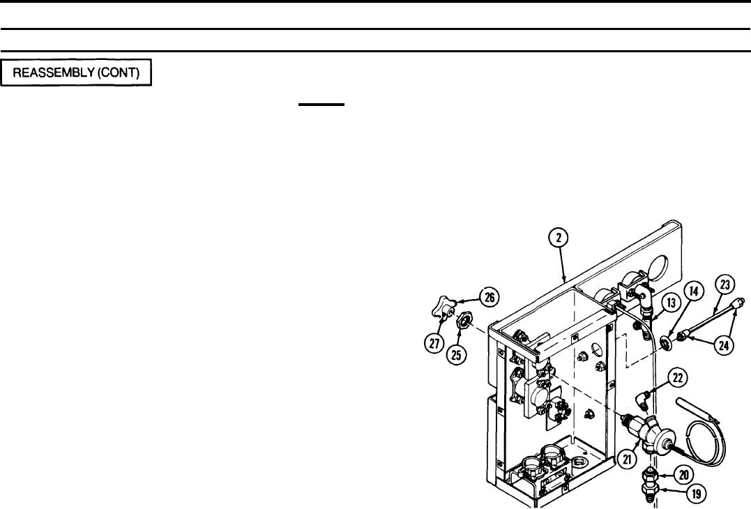
2-33. CONTROL BOX ASSEM BLY (CONT).
REMARKS
ACTION
LOCATION/ITEM
CAUTION
Do not bend or kink capillary tube. Any damage requires
replacement. Do not coil capillary tube in a coil less than 6
inches in diameter while handling it.
Control Box Assembly/
Screw check valve (19) with preformed packing (20) attached into bottom
Check valve (19)
Preformed packing (20)
of temperature regulating valve (21). Wrap male threads of pipe-to-tube
Temperature regulating
elbow (22) with antiseizing tape before screwing into top of temperature
valve (21)
regulating valve (21). Tighten pipe-to-tube elbow (22) so the open end will
Pipe-to-tube elbow (22)
point directly at the nonmetallic grommet (14). Tighten (do not loosen)
pipe-to-tube elbow (22) to aline. Install temperature regulating valve (21),
pipe-to-tube elbow (22), and check valve (19) as a unit into control box (2).
Selector line (23)
Stick selector line (23) through nonmetallic grommet (14) and screw tube
Tube coupling nuts (24)
coupling nuts (24) onto the pipe-to-tube elbow (22) and pipe-to-tube
tee (13) fingertight.
Hexagon plain nut (25)
Install hexagon plain nut (25) onto end of temperature
regulating valve (21 ) and tighten fingertight. Tighten
two tube coupling nuts (24) and hexagon plain nut (25).
Knob (26)
Install knob (26) with setscrew (27) installed. Tighten
Setscrew (27)
setscrew (27).