
TM 3-4230-209-20&P
2-186
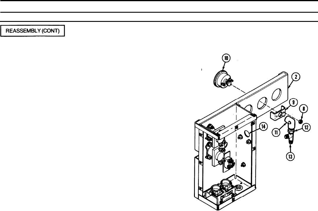
2-33. CONTROL BOX ASSEM BLY (CONT).
REMARKS
ACTION
LOCATION/lTEM
Control Box Assembly/
Nuts (8)
Remove two nuts (8) and metal bracket (9) and install fuel pressure dial
Metal bracket (9)
gage (10) through front of control box assembly (2). Reattach metal
Fuel pressure dial
bracket (9) and secure with two nuts (8).
gage (10)
Wrap all male threads on gages and fittings with antiseizing tape before
installing.
Pipe elbow (11)
Install pipe elbow (11), pipe bushing (1 2), and pipe-to-tube tee (13) as a
Pipe bushing (12)
unit. Point side opening on pipe-to-tube tee toward control box hole for
Pipe-to-tube tee (13)
nonmetallic grommet (14) as shown.
NonmetalIic grommet (14)