
TM 3-4240-284-30&P
2-15. COMPARTMENT CONTROL MODULE - MAINTENANCE INSTRUCTIONS (Cont).
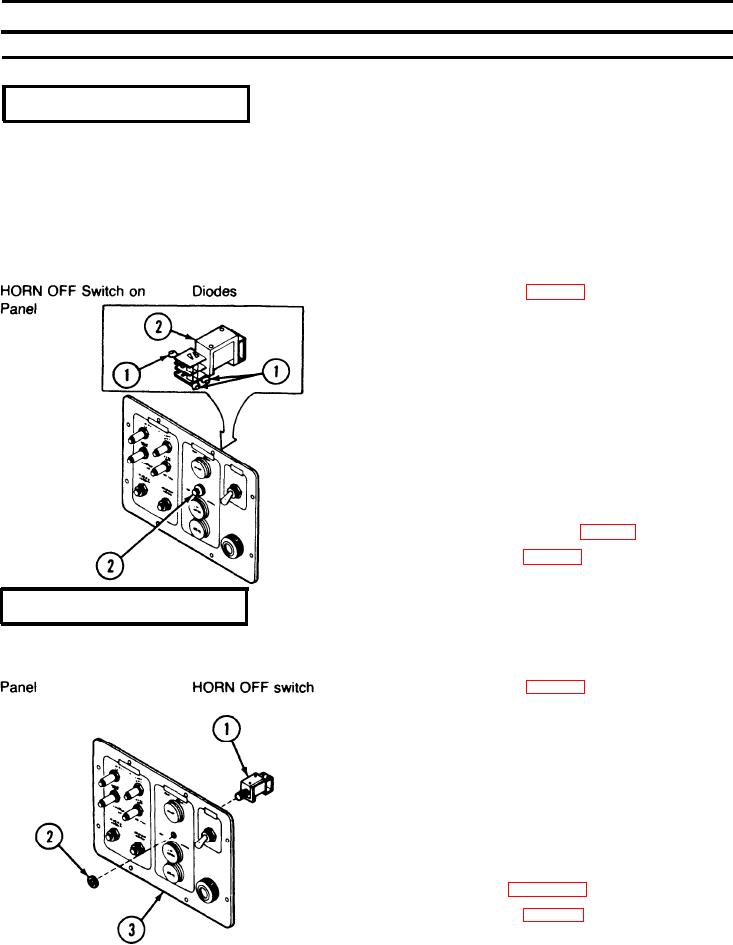
LOCATION
ITEM
ACTION
REMOVAL/INSTALLATION
REMOVAL
CAUTION
When unsoldering diodes (1) from the switch
solenoid terminals, apply needle-nose pliers
to the leads of the diode to form a heat sink.
Excessive heat will damage the diode.
1. Disassemble CCM (p 2-171).
2. Unsolder diodes (1) from HORN OFF switch (2).
INSTALLATION
CAUTION
Diodes must be connected properly or dam- .
age will result. Observe the banded end of
the diodes. Apply needle-nose pliers to leads
of diodes to form a heat sink when soldering.
Excessive heat will damage the diodes.
1. Solder diodes (1) to HORN OFF switch (2) in accor-
dance with wiring diagram (p 2-184).
2. Reassemble CCM (p 2-171).
REMOVAL/INSTALLATION
REMOVAL
1. Disassemble CCM (p 2-171).
2. Unsolder wire leads and diodes from HORN OFF
switch (1).
3. Remove nut (2) and switch (1).
INSTALLATION
1. Insert HORN OFF switch (1) in panel (3) and secure
with nut (2).
2. Connect and solder wires and diodes to HORN OFF
switch. Refer to page 2-184.
3. Reassemble CCM (p 2-171).
2-182