
TM 3-4240-284-30&P
2-15. COMPARTMENT CONTROL MODULE - MAINTENANCE INSTRUCTIONS (Cont).
.
LOCATION
ITEM
ACTION
INSTALLATION
NOTE
Lamp module is keyed to fit into light body at
only one rotational position. it maybe neces-
sary to turn the lamp module within the light
body to find the keyway.
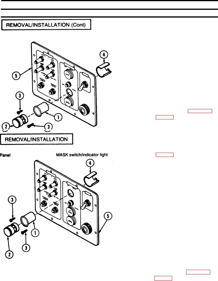
1. Place module (2) in LOW PRESSURE switch/
indicator light (1) and position in panel (5) with the
words LOW PRESSURE right side up and level.
2. Remove module (2). Place sleeve (4) over switch/
indicator light (1) and secure with screws (3).
3. Replace module (2) in switch/indicator light(1).
4. Connect and solder wires. Refer to page 2-184.
5. Reassemble CCM (p 2-171).
REMOVAL
1. Disassemble CCM (p 2-171).
2. Unsolder wire leads from MASK switch/indicator
light (1).
3. Pry out and remove lamp module (2).
4. Remove two screws (3).
5. Remove sleeve (4) and switch/indicator light (1).
INSTALLATION
NOTE
Lamp module is keyed to fit into light body at
only one rotational position. It maybe neces-
sary to turn the lamp module within the light
body to find the keyway.
1. Place module (2) in MASK switch/indicator light(1)
and position in panel (5) with the word MASK right
side up and level.
2. Remove module (2). Place sleeve (4) over switch/
indicator light (1) and secure with screws (3).
3. Replace module (2) in switch/indicator light (1).
4. Connect and solder wires. Refer to page 2-184,
5. Reassemble CCM (p 2-171).
2-181