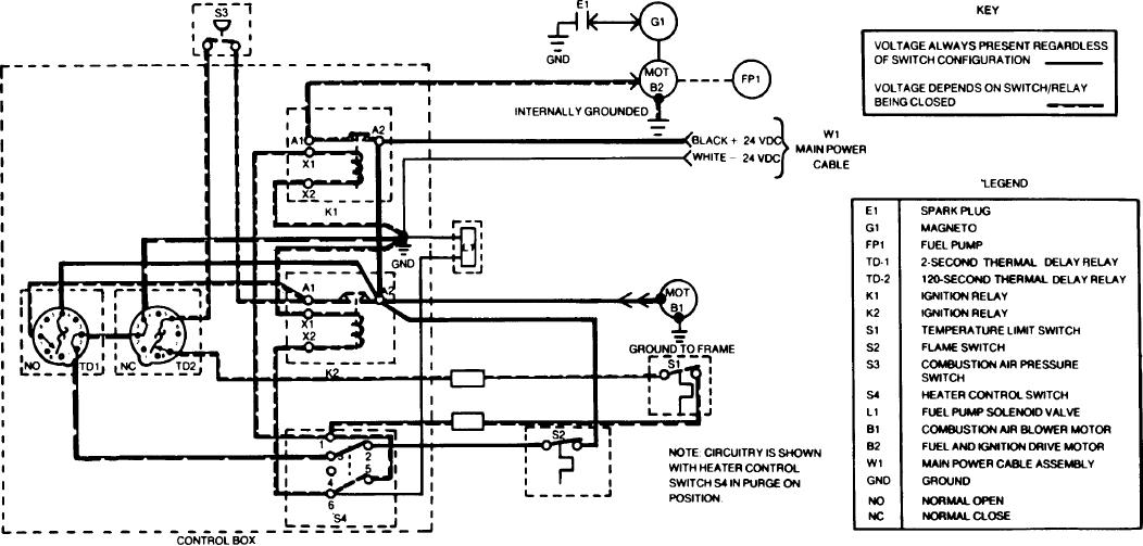
the fuel and ignition drive motor to be powered. Also, the jumper wire from
(9) After approximately 2 seconds the heat from the TD-1 heater
terminal 1 to 5 and out of terminal 6 have power. At terminal 6 there are two
closes the bimetallic contacts on TD-1. As we have indicated before, voltage
branch circuits. The first branch circuit is routed through the fuel pump
has been applied to pin 5 of TD-1 and could not be used because of the open
solenoid valve (L1) which closes routing fuel to the combustor. The second
contact. (Now that the contact closes, the voltage is routed to relay K-2
branch leaves S4 terminal 6 and goes to relay K-2 solenoid (X1-X2) to ground
terminal A1 (K2 deenergized). From A-1 voltage is routed through combustor
and K2 closes. This K-2 closing places a voltage at A2 and also at A1 plus
air pressure switch (S3), thermal delay relay T-D-2 contacts 5 and 7. It continues
through the relay contacts. At this time there should be an indication of fuel
on through the contacts of the temperature limit switch (S1) and back to switch
being ignited in the combustor.
S-4 at terminal 1. As before, voltage from S4-1 closes K-1 solenoid and allows
TM 3-4230-209-20&P
1-19

