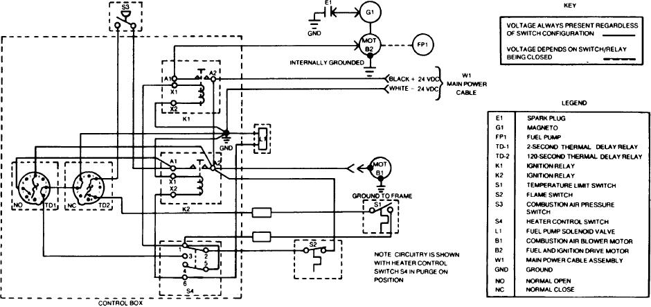
to the fuel pump and ignition drive motor (MOTB2). When the fuel pump and
NOTE
The next few steps are also shown in the schematic form and
ignition drive motor is operating, fuel is pumped from the fuel supply through
the water heater. Since the fuel pump solenoid valve is not powered, all the fuel
these are time cycles.
is returned back to the source. At the same time the magneto is being driven to
produce a very high voltage which is sent to the combustor chamber to the
(6) The main power cable positive (black) wire connects 24 vdc to
igniter (E1) which begins to spark. Any fuel or fuel vapors will be burned off
relays K1-A2, K2-A2, MOT B1 (combustor fan motor) TD1-5, through switch
before additional fuel is supplied. Operate in PURGE ON for at least two
S2 (flame switch) and switch S4-2 (HEATER ON PURGE ON). The power
minutes before moving HEATER ON/PURGE ON SWITCH (S4) to HEATER
should always beat these points regardless of the S4 position. When the
ON. The second branch is a fail-safe circuit. From terminal S4-1 power is
combustor fan (MOT B1) is operating, it will build up a pressure. This pressure
connected through the contacts of S1 (thermostatic switch), located in the top
closes the contacts of S3 (combustion air pressure switch) when pressure is
of the boiler, through pin 7 and 5 of TD-2 (thermal delay-120 seconds), and on
greater than 1 1/4 inches of water (gage).
through S3 which was closed by the air pressure in the terminal combustor
(7) With S4 switch placed to PURGE ON (as shown) the 24 vdc is con-
unit. The voltage leaves S3 and is connected to relay K2 terminal A1 and onto
netted to two branch circuits. The first branch from S4 terminal 1 is connected
pin 7 of TD-1 (thermal delay-2 seconds normally open). This branch is stopped
to relay K1 through X1 and X2 to ground. This closes the contacts to allow the
by the open contacts at both K2-A1 and TD1-7.
24 volts applied to A2 to pass through closed contacts, out terminal A1, and on
1-17
TM 3-4230-209-20&P

