
TM 3-4230-209-20&P
1-16
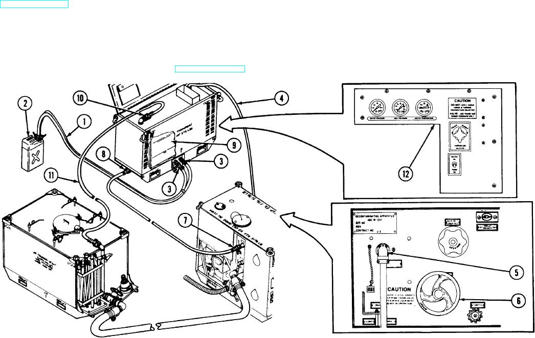
(4) Open VALVE NO. 1 MANIFOLD (6) on pump unit. This routes the
b. Water Heater.
water from the upper DISCHARGE quick disconnect (7) to the lower quick
(1) Fuel (gasoline, diesel fuel, or kerosene), water, and electricity must
disconnect (8) on the heater unit to fill the boiler (9). As water enters the boiler
be supplied to the water heater. Subparagraph a. above and
from the lower quick disconnect, air in top of boiler is forced out of the boiler
TM 3-4230-209-10 cover the water supply.
through the upper quick disconnect (10) and water hose (11) and pumped into
(2) The fuel hose assembly (1) connects a 5-gallon can (2) to the fuel
the tank unit where it is released. When all the air has been expelled, water will
supply and return quick disconnect fittings (3) on the water heater. The free
be transferred back to the tank unit. When water is flowing through the upper
end of the electrical power cable (4), stored in top of the heater, connects the
quick disconnect, the boiler is completely full of water and safe to start heating
water heater to the pump unit HEATER RECEPTACLE AND SWITCH OFF/
operations.
ON (5).
(5) Placing the pump unit HEATER RECEPTACLE AND SWITCH
(3) With the electrical power cable (4), fuel hose assembly (1), and all
OFF/ON (5) to ON routes the 24 vdc power to the heater control box
hoses connected for the mode operation needed (see TM 3-4230-209-10) and
assembly (12) on the water heater.
the pump running at 3850 RPM, the heater unit can be powered up.