4-7. Lines and Fittings
a. Removal.
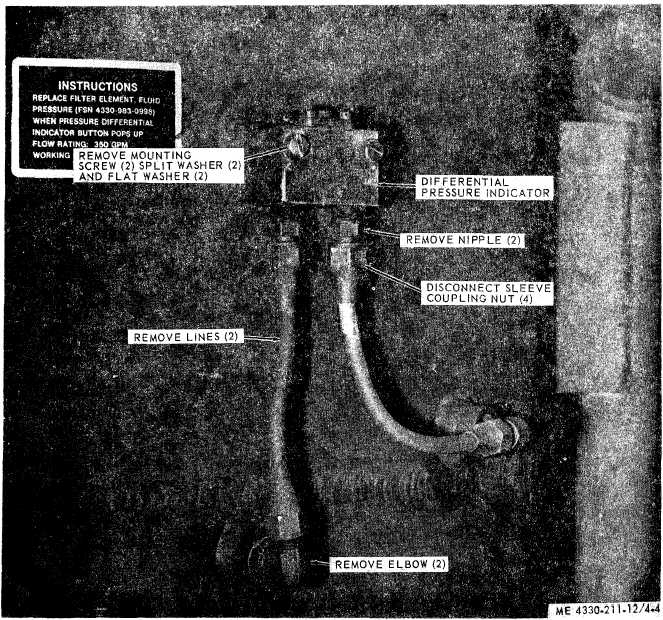
Remove lines and fittings as
N O T E
shown in figure 4-4. Fabricate new lines as re-
quired.
These lines are the inlet and outlet lines for the
b. Installation. Install the lines and fittings
differential pressure indicator.
in reverse order of removal.
Figure 4-4. Differential pressure indicator, lines, and fittings.
4-8. Differential Pressure Indicator
sure line 20 PSI and see if the differential pres-
a. Removal. Refer to figure 4-4 and remove
sure indicator (raising of the signal button)
the differential pressure indicator.
works properly. Replace a defective differential
b. Testing.
pressure indicator.
(1) Connect a compressed air line to high
c.
Installation.
and low pressure lines.
(1) Refer to figure 4-4 and install the dif-
(2) Maintain an equal pressure on both
ferential pressure indicator in reverse order of
lines then reduce air pressure in the low pres-
removal.
4 - 5