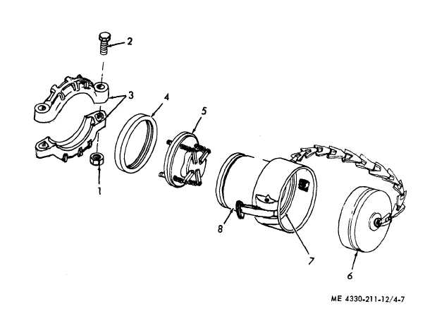
1 Nut
3 Coupling clamp
5 Flow limiter
2 Bolt
4 Gasket, coupling clamp
6 Dust plug
7 Gasket, coupling half
8 Coupling half
Figure 4-7. Coupling ha[f and flow limiter, exploded view.
4-12. Flow Limiter
c. Installation. Refer to figure 4-6 and 4-7
a. General. The function of the flow limiter
is to prevent the filter-separator flow rate from
exceeding 350 GPM. The flow limiter consists of
an orifice plate to which a spring loaded baffle
plate is mounted. The flow limiter is designed
so that its pressure differential increases gradu-
ally with the increased flow to the trigger point
(approximately 370 GPM). The baffle plate
closes to within 1/16 inch of the orifice plate
and reduces the flow to 350 GPM.
b. Removal. Refer to figure 4-6 and 4-7 and
remove the flow limiter as instructed.
and install the flow limiter in reverse order of
removal.
4-13. Outlet Port Service
a. Refer to paragraph 3-2d and remove the
filter elements and canisters as instructed.
b. Refer to figure 4-8 and service outlet port
as instructed.
c. Refer to paragraph 3-2d and install filter
elements and canisters as instructed.
4-8


