
TM 3-4240-284-30&P
2-9. PROTECTIVE ENTRANCE CONTROL MODULE - MAINTENANCE INSTRUCTIONS (Cont).
ACTION
ITEM
LOCATION
REMOVAL/INSTALLATION
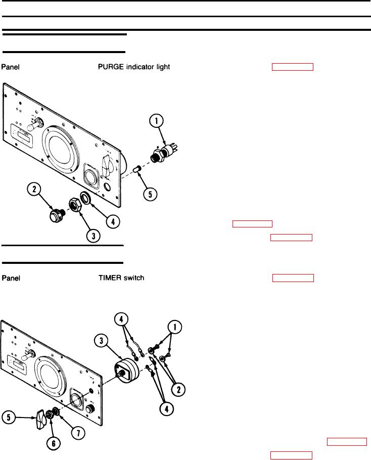
REMOVAL
1. Disassemble PECM (page 2-137).
2. Remove insulating tubing and unsolder wires from
PURGE indicator light (1).
3. Unscrew knurled lens (2) and nut (3).
4. Remove washer (4) and PURGE indicator light (1).
5. Remove lamp (5) from lens ( 2).
INSTALLATION
1. Install lamp (5) in lens ( 2).
2. Insert PURGE indicator light in panel and install
washer (4) and nut (3).
3. Install knurled lens (2).
4. Place insulating tubing over wires.
5. Connect and solder wires to PURGE indicator light.
Refer to page 2-142.
6. Reassemble PECM (page 2-137).
REMOVAL/lNSTALLATION
REMOVAL
1. Disassemble PECM (page 2-137).
2. Remove two screws (1) and two washers (2) from
TIMER switch (3). Remove wires (4).
3. P u l l off knob (5).
4. Remove nut (6) and washer (7) from TIMER
switch (3).
5. Remove TIMER switch (3).
INSTALLATION
1. Install TIMER switch (3) in panel using washer (7)
and nut (6).
2. Push knob (5) on shaft of TIMER switch.
3. Install wire leads (4) on TIMER switch using
washers (2) and screws (1). Refer to page 2-142.
4. Reassemble PECM (page 2-137).
2-139