
TM 34240-284-30&P
Section II. MAINTENANCE PROCEDURES FOR M10 PROTECTIVE ENTRANCE
c. Illustrations are configured to show access to the
2-8. Scope.
.
specific components being-addressed and may not
a. This section contains repair procedures for com-
show the true position of the item or items being main-
Ponent Parts of the M10 protective entrance.
tained or disassembled.
b. Disassemble only as necessary to gain access to
d. Identify wiring prior to unsoldering connection to
desired components.
simplify reassembly.
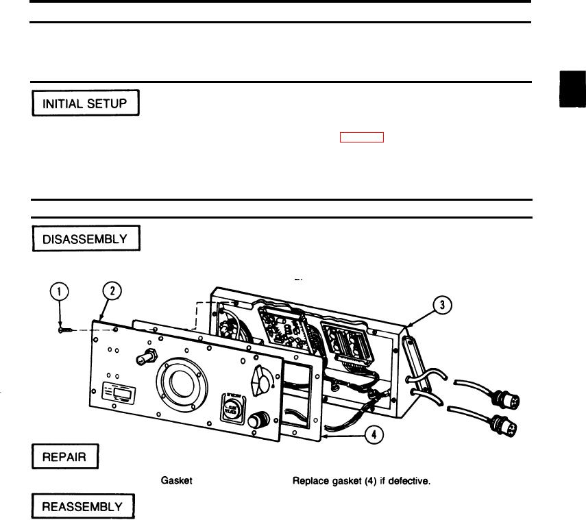
2-9. PROTECTIVE ENTRANCE CONTROL MODULE - MAINTENANCE INSTRUCTIONS.
This task covers:
d. Removal
a. Disassembly
e. Installation
b. Repair
c. Reassembly
Troubleshooting References
Tools
Refer to page 2-2.
Electronic Equipment Tool
Kit TK-105/G (SC 5180-91-CL-R07)
Equipment Condition
PECM removed from the protective entrance.
References
TB SIG 222
ACTION
ITEM
LOCATION
Protective entrance control 1. Remove twelve screws (1) from panel (2).
module
2 Carefully pull panel (2) away from housing (3).
1. Place panel (2) on housing (3) and secure with
Protective entrance control
module
twelve screws (1).
2-137