
TM 3-4240-284-30&P
2-9. PROTECTIVE ENTRANCE CONTROL MODULE - MAINTENANCE INSTRUCTIONS (Cont).
ACTION
ITEM
LOCATION
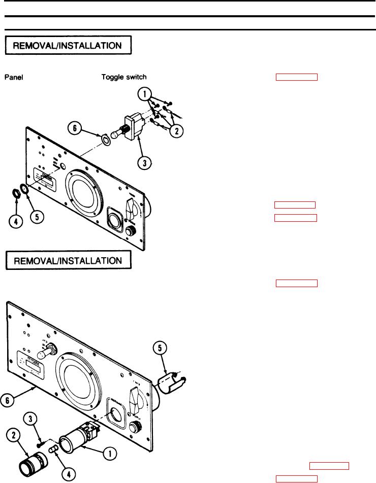
REMOVAL
1. Disassemble PECM (page 2-137).
2. Remove three screws (1) and wires (2) from toggle
switch (3).
3. Remove nut (4) and washer (5).
4. Remove toggle switch (3) and keying washer (6).
INSTALLATION
1. Install keying washer (6) on toggle switch (3).
2. Insert toggle switch in panel and secure with
washer (5) and nut (4).
3. Attach wires (2) to toggle switch using three
screws (1). Refer to page 2-142.
4. Reassemble PECM (page 2-137).
REMOVAL
1. Disassemble PECM (page 2-137).
LOW PRESSURE
Panel
switch/indicator
2. Unsolder wires from LOW PRESSURE switch/
indicator light (1).
3. Pry out lamp module (2).
4. Remove two screws (3) and two lamps (4).
5. Remove sleeve (5) from back of panel (6) and pull
LOW PRESSURE switch/indicator light (1 ) from
front of panel (6).
INSTALLATION
1. Insert LOW PRESSURE switch/indicator light (1) in
panel.
2. Place sleeve (5) over LOW PRESSURE switch/
indicator light and secure with screws (3). Install
lamps (4).
3. Press lamp module (2) into LOW PRESSURE
switch/indicator light.
4. Connect and solder wires to LOW PRESSURE
switch/indicator light. Refer to page 2-142.
5. Reassemble PECM (page 2-137).
2-138