2-104
TM 3-4230-209-20&P
2-25. THROTTLE LINKAGE ASSEMBLY (CONT).
ACTION
REMARKS
LOCATION/lTEM
Throttle Linkage Assembly/
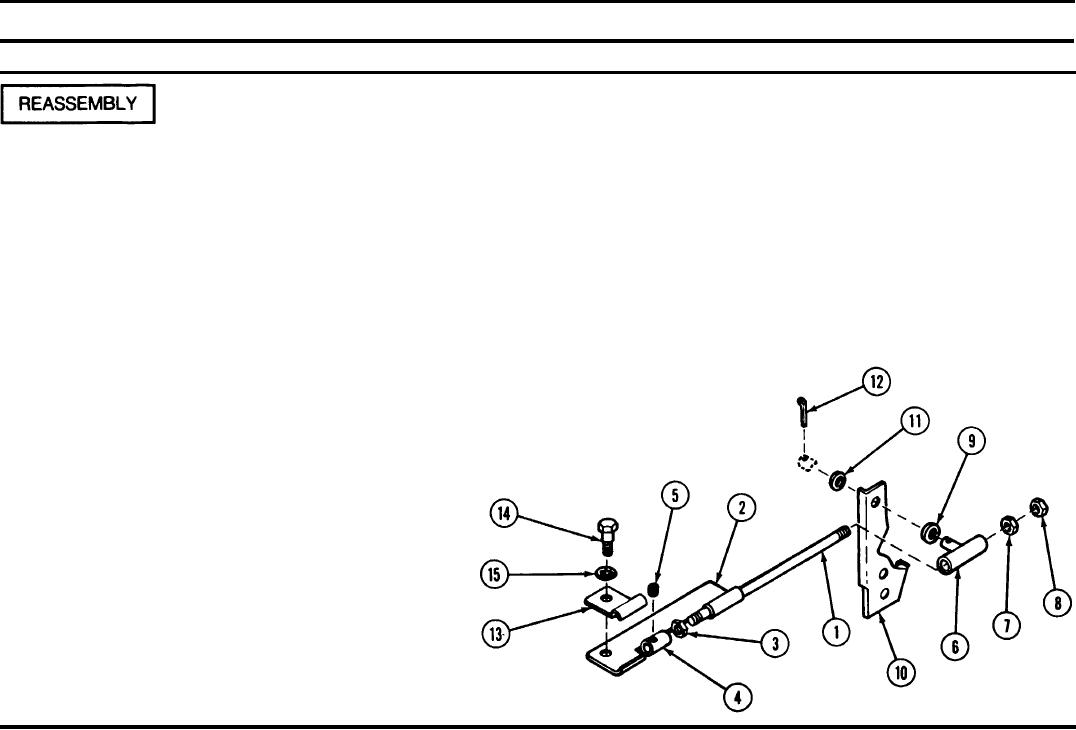
Insert the end of throttle rod (1) with the fewest threads into loop
Throttle rod (1)
Loop clamp (2)
clamp (2). Screw hexagon plain nut (3) on throttle rod (1) up to the end of
the threads. Screw throttle adapter (4) on throttle rod (1) until it bottoms.
Hexagon plain nut (3)
Screw hexagon plain nut (3) against throttle adapter (4) and tighten. Install
Throttle adapter (4)
setscrew (5) loosely.
Setscrew (5)
Swivel (6)
Slide swivel (6) over throttle rod (1) and screw on hexagon plain nuts (7
and 8). Tighten hexagon plain nuts (7 and 8) against each other at outer
Hexagon plain nuts (7
end of throttle rod (1). Place flat washer (9), remote control lever (10), and
and 8)
flat washer (11) on stud of swivel (6). Secure with cotter pin (12).
Flat washer (9)
Remote control lever (10)
Flat washer (11)
Cotter pin (12)
Retaining strap (13), hexagon head cap screw (14), and internal tooth lock
Retaining strap (13)
Hexagon head cap
washer (15) must be attached, shipped, and taped to the throttle linkage
screw (14)
assembly. A hexagon nut can be used to secure items (13, 14, and 15) for
Internal tooth lock
shipment.
washer (15)

