TM 10-4330-236-13&P
4-14.
LATCH PIN, LATCH PLATE AND JUMPER CABLE REPLACEMENT.
This task consists of:
a
Removal
b.
Installation
INITIAL SET-UP:
Tools
Equipment Conditions - continued
General Mechanics Tool Kit (Appendix B, Section
Air duct disconnected from defrost shroud. Refer to para
III Item 1)
2-6.
Defrost door and shroud removed. Refer to para 4-13.
Materials/Parts
Lock washers (Appendix C, Section I)
General Safety Instructions
Equipment Conditions
WARNINGS
Filter-separator removed from system. Refer to
· Do not smoke within 100 feet of filter-separator.
para 2-6.
· Fuel is toxic to skin, eyes, and respiratory tract.
Air vent valve open. Refer to para 2-6.
a.
Latch Pin and Latch Plate
. Refer to figure 4-4.
NOTE
Latch pins and latch plates are located in four places on the 200 gpm filter-separator. This
procedure is typical for all latch plates.
(1)
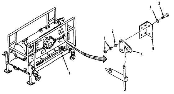
Removal. Remove four nuts (1), two lock washers (2), two screws (3), two flat washers (4), and latch
plate (5) from shroud bracket (6) on shroud assembly (7).
(2)
Installation. Install plate (5), two screws (3), two flat washers(4), two lock washers (2), and two nuts (1)
onto shroud bracket (6).
Figure 4-4. Latch Pin and Latch Plate Replacement.
4-9