
TM 3-4240-286-20&P
2- 24. CABLE C5- 19- 6160- 50 - MAINTENANCE INSTRUCTIONS.
This task covers:
c. Replace
a. Removal
d. Installation
b. Test
INITIAL SETUP
Test Equipment
Multimeter AN/USM223
ACTION
ITEM
LOCATION
REMOVAL
WARNING
Before removing protective entrance cables, be sure that POWER switch on the compartment control
module is in the OFF position and that the collective protection equipment power source is shutdown.
Set compartment control module POWER switch (1)
Cable C5-19-6160-50
Compartment Control
to OFF.
Module and Feed-Thru*
Connector
Shut down collective protectection equipment
power source.
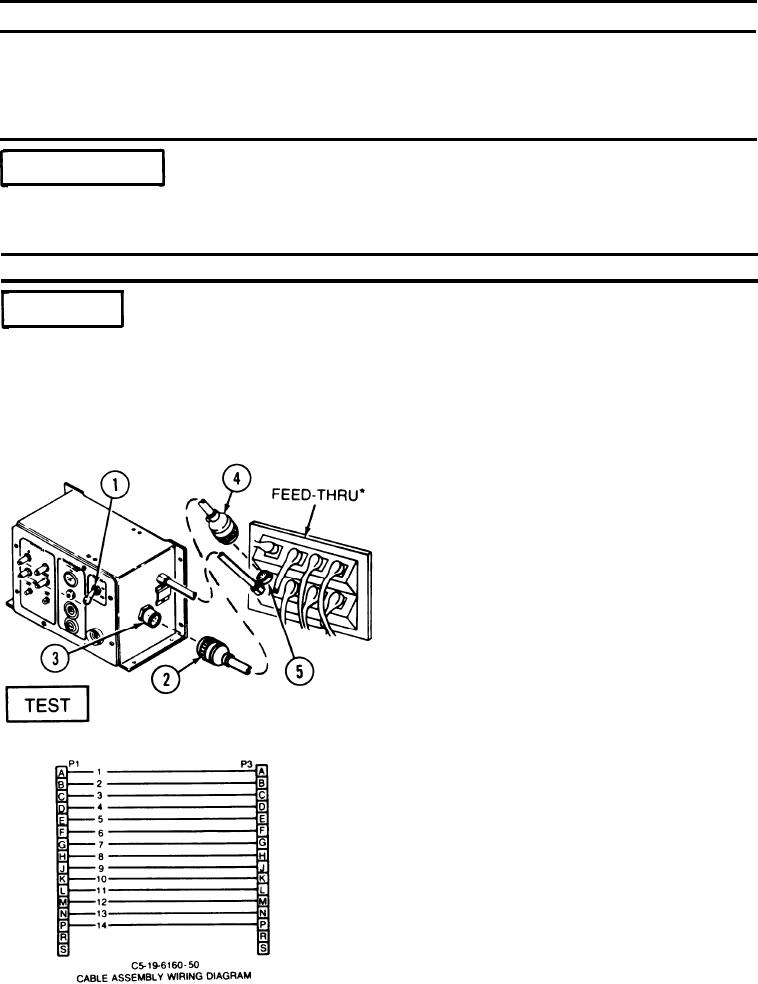
Disconnect cable assembly plug P1 (2) from
compartment control module connector J1 (3).
Disconnect cable assembly plug P3 (4) from feed-thru*
connector J3 (5).
Check continuity of each wire between P1 and P3.
Cable C5-19-6160-50
NOTE
Use multimeter and cable C5-19-6160-50
wiring diagram.
*MCPE/DISPLAY DEMARK
2-102