
TM 3-4240-284-30&P
2-12. AIRFLOW VALVE - MAINTENANCE INSTRUCTIONS (Cont).
.
ACTION
ITEM
LOCATION
REMOVAL/INSTALLATION
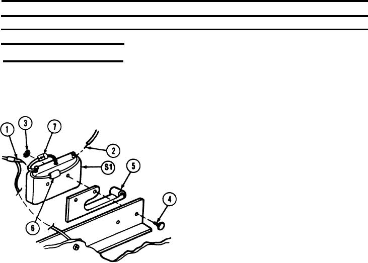
REMOVAL
1. Tag and unsolder wire (1) from normally closed (NC)
Airflow Valve
Switch (S1 ) and adapter
terminal on switch (S1 ).
2. Tag and unsolder wire (2) from common (C) terminal
on switch (S1 ).
3. Remove two nuts (3) and screw (4).
4. Remove switch (S1) and adapter (5).
INSTALLATION
1. Install switch (S1 ) and adapter (5) using two
screws (4) and nuts (3).
2. Cut and bend leads of capacitor (6) to fit between
normally closed (NC) and common (C) terminals of
switch (S1 ).
3. Cut and bend leads of diode (7) to fit between nor-
mally closed (NC) and normally open (NO) terminals
of switch (S1 ).
4. Solder wire (1), one end of capacitor (6), and one
end of diode (7) to normally closed (NC) terminal of
switch (S1 ).
5. Solder wire (2) and one end of capacitor (6) to com-
mon (C) terminal of switch (S1 ).
6. Solder one end of diode (7) to normally open (NO)
terminal of switch (S1 ).
2-157