
TM
3-4240-284-20&P
Section III. PRINCIPLES OF OPERATION
nents in compartment control module
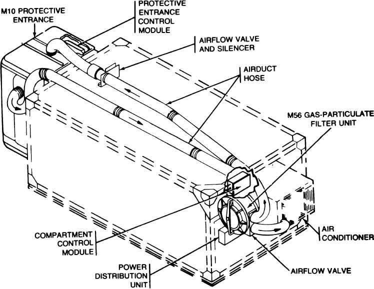
1-11. AIR FILTERING AND PRESSURERIZATION
automatically adjust the airflow valve to
SYSTEM.
maintain a positive pressure in the shelter
a The M56 gas-particulate filter unit removes
b. The M10 protective entrance provides a
toxic gases and dust from air supplied to
the M10 protective entrance and shelter.
pressurized transition area between the shel-
Outside and are drawn through the
ter and the outside contaminated zone. Per-
air inlet of the by the main fan.
sonnel entering from the outside must wait
From the main fan, the air is pushed through
five minutes within the protective en-
before entering the shelter. Contamination is
the particulate and gas filter to the airflow
valve. The filtered air passes through the
purged by the flow of the filtered air. The
airflow valve and is carried by airduct hoses to
protective entrance control module au-
the protective entrance through the airflow
tomatically adjustS the airflow valve and si-
valve and silencer and to the shelter through
lencer assembly to maintain the proper air
the air conditioner. Pressure sensing compo-
pressure inside the protective entrance.
1-8