
CHAPTER 2
OPERATING INSTRUCTIONS
Section I. CONTROLS AND ANCILLARY ASSEMBLIES
(2) Purpose. The choke controls the flow of air
9.
General
into the carburetor. It is also used to enrich
This section describes, locates, illustrates, and
the fuel-air mixture when starting the
furnishes the operator sufficient information pertaining to
engine.
the various controls and instruments provided for the
proper operation of the ABCM6A1 filter unit.
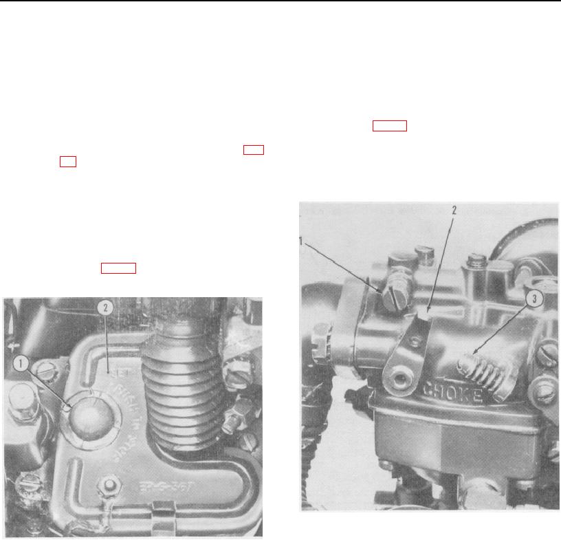
c. Idle Speed Regulating Screw.
10.
Controls
(1) Location. The idle speed regulating screw
(3, fig. 12) is located in the upper carburetor
a. Engine Stop Button.
body.
(1) Location. The engine stop button (1, fig.
(2) Purpose. The idle speed regulating screw
11) is mounted on the engine accessory
is used to adjust the idling speed of the
case cover (2).
engine.
(2) Purpose. The stop button stops the engine
by grounding the ignition.
b. Choke Control Lever.
(1) Location. The carburetor choke control
lever (2, fig. 12) is located in the carburetor
air intake.
Idle adjustment needle
3
Idle speed regulating
2
Choke control lever
screw
1. Engine stop button
2
Accessory case cover
Figure 12. Carburetor choke control and adjustment.
Figure 11. Engine stop button
12

